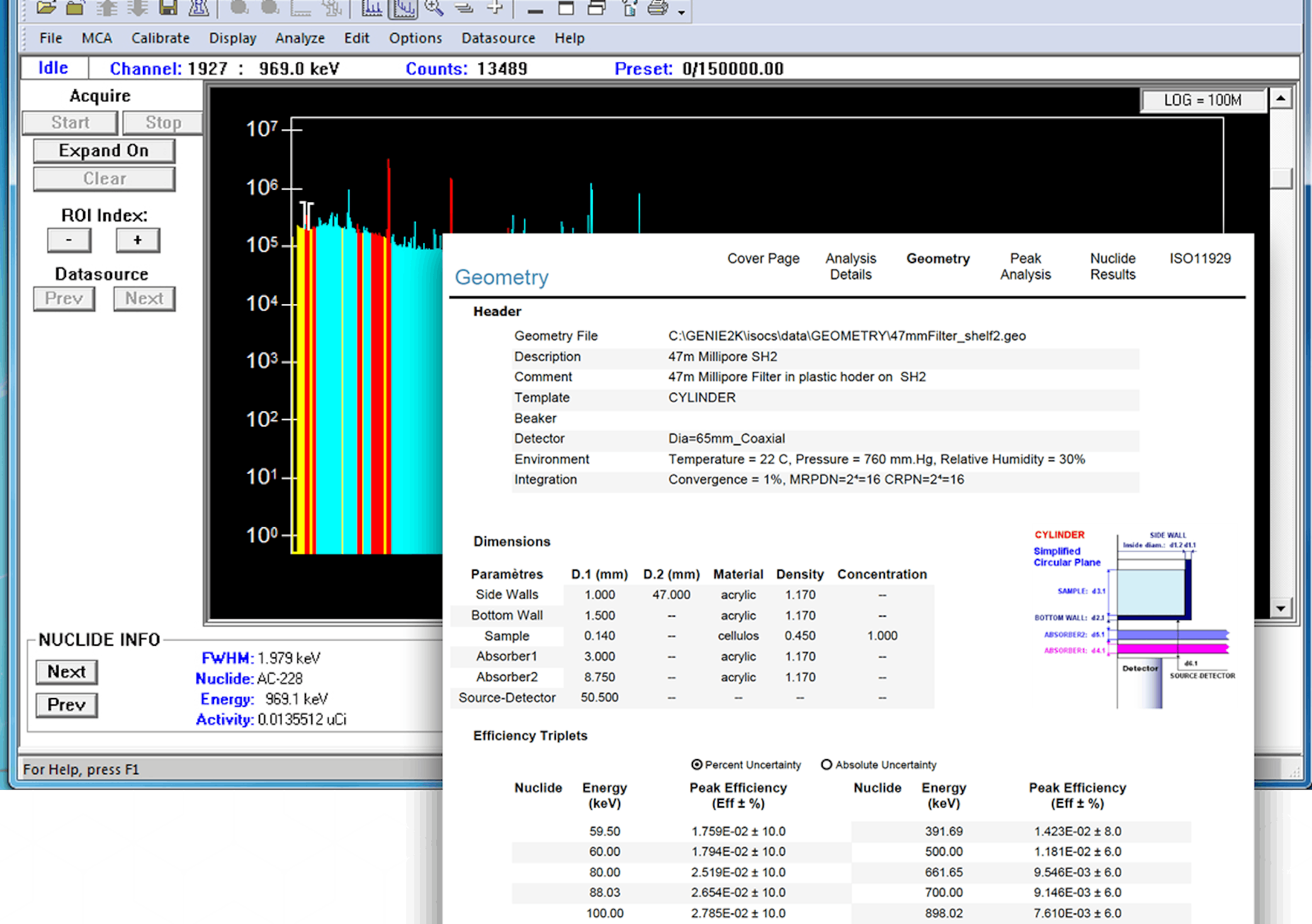
G64 Gamma Monitor
|
Features
- Solid state detector: range 0.1 μSv/h to 100 mSv/h (10 μR/hr–10 R/hr)
- Pseudo-logarithmic ratemeter averaging for good statistics at low level and fast response at high levels
- Removable detector unit for remote use
- Ion chamber detector option for high range applications 100 μSv/h to 100 Sv/h (10 mR/hr–10 kR/hr)
- SC & GM options available for use with customer’s own scintillation or GM probes
- Three user-set alarm levels across the full range
- Local signalling by audio and visual alarms
- Remote signalling by relays, 4–20 mA and RS-485 communications outputs
- Displays on analogue meter and LCD
- Status, fault and alarm messages shown clearly
- Membrane push buttons allow alarm mute and reset
- Keypad allows parameter adjustment
- Interlock monitor functionality
- Front panel RS-232 port for configuration by local PC
- Optional iConfig PDA configuration unit
Description
The G64 Area Gamma Monitor is a compact, mains-powered, microprocessor-based radiation monitor, designed specifically for area and process monitoring in nuclear facilities. Its main functions are to display the gamma dose rate in the area and to warn local personnel in the event of an alarm situation. It can also function as an interlock monitor.
The G64 is intended for installed use but can also be used on a bench stand or wheeled trolley to provide temporary monitoring or to supplement permanently installed monitors during maintenance activities. The only requirements of the basic system are a G64 monitor, suitably mounted (wall mounting brackets supplied), and a mains power supply in the range 100-240 V ac.
The standard G64 is supplied with a compact solid state detector for use in low to medium dose rate applications. The detector is directly mounted on top of the display/alarm unit. For remote monitoring applications, the detector assembly can be easily dismounted from the display/alarm unit and installed at distances of up to 100 m (328 ft) using a Remote Detector Kit. The user must simply ensure that connections between the detector and the G64 display/alarm unit are correct and that the detector is mounted using the wall mounting bracket supplied.
The G64 is also available in three other versions for additional applications:
- G64IC: for high dose rate and high integrated dose applications. Supplied with a remotely mounted ion chamber detector, 10 m (33 ft) dual coaxial detector cable and a remote amplifier/interface unit.
- G64SC: intended for use with existing scintillation detectors and therefore not supplied with a detector. Scaled in cps – kcps and supplied with a remote scintillation detector amplifier/interface unit for connection to customer’s own installed detector.
- G64GM: primarily intended for use with existing GM probes and therefore not supplied with detectors equipped with a remote GM detector amplifier/interface unit for connection to customer’s own installed GM detector.
Operating Principle
A block diagram of the G64 with solid state detector is shown below. Gamma radiation interactions in the G64 solid state detector produce charge pulses whose magnitude and frequency are proportional to the incident energy and dose rate. These charge pulses are amplified and shaped to produce a series of voltage pulses, each of which, if it is above the minimum energy that the G64 has been designed to detect, triggers an RS-422 pulse which is sent to a scaler. The scaler contents are read out at regular intervals by a microprocessor and converted to the corresponding radiation dose rate. An adaptive software algorithm is used to ensure both a rapid response to step changes and good statistical accuracy, even at low dose rate levels. The microprocessor controls the G64’s indicators, alarm annunciators and external communications.
Ion Chamber Detector
The G64 Ion Chamber Detector is a small, environmentally-sealed (IP65) gamma radiation detector, which is designed to replace the standard solid state semi-conductor detector in high dose/high dose rate environments.
The detector (inside the high dose rate environment) is connected to its remote amplifier/interface unit (outside the high dose rate environment) by 10 m (33 ft) of special connecting cable (supplied). The amplifier/interface supplies the high voltage required by the ion chamber and converts the low level current signal to a frequency signal for transmission to the G64 display/alarm unit via up to 50 m (164 ft) of standard twin twisted pair cable. The amplifier/interface unit also receives 12 V dc power from the G64 display/alarm unit via this cable. In low dose rate areas (<20 μSv/hr) the G64IC ion chamber may need an internal 18 kBq (0.5 μCi) 241Am holdup source installed inside in order to give a constant indication that the detector is operating (as required under International Standards for Monitors).
G64 SC and GM Systems
Both of these systems are supplied without detectors, as their primary purpose is to replace or upgrade old system electronics where the customer desires to retain the existing detector. Each system has a remote amplifier/interface unit designed to supply the high voltage required by the detector and amplify the detector pulses and convert them to RS-422 format for transmission to the G64 display/alarm unit. Both the SC and GM amplifier/interface units have a very wide range of gain and high voltage settings, to allow them to be set up to match a wide variety of scintillation or GM detectors.
Configuration
The G64 incorporates a universal power supply
that operates over the mains range 100-240 V ac.
Therefore, no switches or links are required to operate
at any voltage within this range. On power-up, the
G64 will perform a self-test and when this has been
successfully completed it will commence monitoring.
The G64 can be configured via the front panel RS-232 port using the PC Config software supplied with the unit or the optional iConfig PDA. This software allows access to all user-settable parameters. In addition, the most commonly accessed parameters (e.g. alarm levels) can be accessed via the front panel keys using a ‘hidden’ passcode key sequence. This access can be disabled for additional security if required.
Parameters accessible via the keypad include:
- detector type, calibration factor and dead time
- alarm levels and responses
- fault condition responses
- alarm level detection factor
- high alarm delay time
- detector nil-count timeout period
- analogue output (4-20 mA) start decade and range (number of decades)
- averaging algorithm to be used (pseudo-log or fixed time).
The status of the operating parameters may be viewed at any time by means of soft keys and the LCD display on the front panel.
In the event of an alarm situation, two soft keys are available on the front panel to allow the user to mute the sounder (the beacon continues to flash) or to reset the instrument.
Using a Remote Detector
To remove the detector assembly, simply open the front panel of the G64, pull out the retaining pin and unplug the assembly from the top of the unit. Install and connect the detector using a G64 Remote Detector Kit, which consists of:
- detector mounting bracket
- cover plate for top of main G64 unit
- cable (standard lengths 10 m, 25 m or 100 m), terminated with a 9-way D-type connector that plugs directly into the remote detector.
The flying lead of the cable is connected to the screw terminal block within the instrument. The cable is a twin twisted pair; two wires for DC power and two for RS-422 pulses from the detector. The same cable connection is used for the IC, SC and GM remote amplifiers/interfaces.
Indicators
Two displays indicate the dose rate:
- a moving coil analogue meter with a 6-decade log scale, which can be viewed from a distance
- a 16 character x 2 line liquid crystal display (LCD) provides a more precise indication of the dose rate. It is permanently backlit for easy viewing.
Both displays indicate the current alarm level setting when the corresponding soft key is pressed. The LCD also indicates the current system parameters when the ‘scroll data’ soft key is pressed.
When the G64 is operating normally, the green beacon will be constantly illuminated. The G64 has three light emitting diodes (LEDs) located above the analogue meter, which indicate whether it is normally operational, in a fault condition or working off its internal battery (‘AC fail’).
Alarms and Annunciators
The G64 has three alarm thresholds, all of which
are user settable. The ‘alert’ and ’high’ alarms are
triggered when the ambient radiation level exceeds
these thresholds. Both can be set across the range of
the instrument, although the alert level must always
be less than the high level. The user can select
which annunciators are associated with these alarms,
whether they are to be latched or unlatched, and what
detection factor is to be applied.
The detection factor allows the user to set thresholds at a fixed number of standard deviations above and below each alarm level to provide confidence that an alarm is genuine rather than a statistical fluctuation.
For example, if an alarm level in μSv/h is equivalent to 100 cps recorded in the detector and the detection factor is set to 2 sigma, then the alarm will be generated when the count rate exceeds 120 cps and will be maintained until it falls below 80 cps. The ‘low’ alarm threshold differs from the other two in that, in this case, the alarm is triggered if the radiation falls below this level. Its main purpose is to identify a detector failure and it therefore shares the same relay as the equipment fault.
Alarm annunciation is by means of:
- the red beacon, which flashes
- the sounder, which can be configured by the user to one of 24 different tones and frequencies (e.g. to avoid confusion with other plant devices) via switches accessible behind the front door. LEDs, located below the LCD, indicate which of the three alarm conditions has been registered. The user may suppress alarm annunciation for either or both of the activity alarms if required.
In the event of a sustained mains failure, full operation is supported by an internal battery for at least 30 minutes.
Outputs and Communications
Connections to the G64 are via unplugable screw terminal blocks, accessible, with the front panel open, through compression glands on the underside of the instrument. The G64 enables the user to control external devices and to transmit data to local or remote locations via:
- three sets of volt-free changeover contacts for the alert and high activity alarms and the low activity alarm/equipment fault condition. Relays can be configured to operate in the fail-safe mode, i.e. normally energized (default setting) or in normally de-energized mode
- RS-232 serial port for communication to local PC or PDA
- RS-485 serial port for communication with remote monitoring systems
- current loop output for driving a chart recorder
- RS-422 pulse output for connection to distributed control systems.
Diagnostics
The G64 incorporates a number of hardware and software diagnostics to identify the nature of any fault in the operation of the instrument. Faults that will be detected are:
- 5 V, 12 V or 24 V dc line fault (check)
- low internal battery voltage
- detector fault
- mains failure
- microprocessor fault
Occurrence of any of these conditions will cause the green beacon to flash and will trip the ‘equipment fault’ relay. The nature of the fault will be displayed on the LCD.
The G64 includes a back-up battery to provide up to 5 seconds immunity to temporary mains interruptions and up to 30 minutes of full operation (with AC fail indication) if the interruption is sustained. During this period it will emit a constant audio tone and flashing green beacon and the ‘AC fail’ LED will be illuminated.
G64 Interlock Monitor
The three sets of volts-free changeover contacts provided in the monitor can be configured for interlock control. In these applications the beacons may be removed if not required, and the sounder disabled.
Related Equipment
D1 Slave Alarm
The D1 Slave Alarm is designed for use with any monitoring instrument, including the G64 Area Gamma Monitor, whose output provides a pair of volts-free relay contacts. In its standard configuration the Slave Alarm is actuated when the relay contacts open, signalling the alarm condition with an audio sounder and a flashing red beacon. The D1 is mains powered and can be set for use with a 110 V or 240 V ac power supply.
RADACS™
G64 is compatible with CANBERRA’s RADACS
environmental surveillance and monitoring software.
RADACS allows the implementation of large networks
of varied monitoring instruments to provide total
surveillance and control of radiological conditions
throughout plants and facilities.
Accessories
- remote Detector Kit (10 m, 25 m, 100 m) (33 ft, 82 ft, 328 ft) includes pre-terminated cable, blanking plate and wall mount for detector
- bench stand with RCD and MCB – 110 V ac or 240 V ac versions (/B110 or /B240 option)
- trolley mount with RCD and MCB – 110 V ac or 240 V ac versions (/T110 or /T240 option)
- test pulse generator
|
| Top of Page |
Related Products
